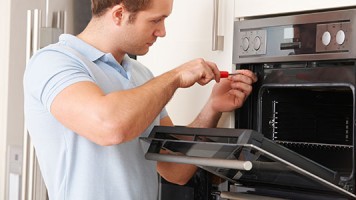
Hi Folks,
This dryer was in a very poor condition. The pulley had fallen off the fan and the owner kept using it with no circulation of heat. No fuses were found to be defective. Element checks out! Proceeded to clean the unit thoroughly. Took care of the pulley and circulation problems. Put it all back together and no heat. Check the board and it was fried. Installed a new board and still no heat. There was no tech sheet with the unit! Now I have 240v going to the board (two legs of 120v each) but where do I find the legs coming out. It’s the heating cycle because the dryer is turning but no heat. I need a tech sheet and some expertise on getting this unit on board!
Thank you,
Jan
Barney’s Appliance
Fixed the air circulation problem. Board was fried, installed new board.
- Guest asked 10 years ago
HI. Below is the steps to take for a no heat symptom on this dryer. Was the dryer heating before you made the repairs on it? I will work on sending the tech sheet to you. Double check your fuse on the blower housing, and the hi limit fuse and t-stat on your heater box. IF theses are good then see what kind of voltage you get at your heat element. Following the steps below if you need further assistance and let me know what you find.
TEST #4 Heater
This test is performed when either of the following
situations occur:
✓ Dryer does not heat
✓ Heat will not shut off
✓ Display flashes L2
This test checks the components making up the heating
circuit. The following items are part of this system:
– Harness/connection – Centrifugal switch
– Heater relay – Exhaust thermistor
– Thermal cut-off – Machine control
– Inlet thermistor/ electronics. See ESD
high limit thermostat information, page 1.
– Heat element – User interface
assembly assembly
Dryer does not heat or display flashes L2:
1. Unplug dryer or disconnect power.
2. Remove the front panel and drum assembly to
access the thermal components. See Removing
the Front Panel/Drum Assembly, page 8.
3. Using an ohmmeter measure
the resistance across the high limit thermostat.
If an open circuit is not detected, go to step 5.
If an open circuit is detected, go to step 4.
4. Visually check the wire connections to the thermal
cut-off and the high limit thermostat. If
connections look good, check for continuity across
each of these components. Replace both the
thermal cut-off and the inlet thermistor/high limit
thermostat assembly if either the thermal cut-off
or the high limit thermostat is electrically open.
5. Measure the resistance between the red wires
at the heater.
If an open circuit is not detected: Go to step 7.
If an open circuit is detected, go to step 6.
6. Visually check the wire connections to the heater.
If the connections look good, replace the heater
assembly.
7. Visually check connections at the machine control
electronics. If the connections look good, and an
open circuit was not previously detected at the
heater, remove the P4 connector, then measure
the resistance between P4-3 (red wire) and P4-6
(red wire) at the connector. See figure 16, page 9
for connector location; and Accessing & Removing
the Electronic Assemblies, page 8.
If 5–15 kΩ are measured, replace the machine
control electronics.
If the resistance is less than 1 kΩ, replace the
exhaust thermistor.
Heat
- Brian, Ace Appliance answered 10 years ago
-
Hi Brian, I am getting 240v going into the board! Where does the voltage come out at the board for L1 & L2? Thank you, JAN
-
The heat relay on the board has a red and black wire going to it. It should have 240v. When you press the start button on a heat cycle, it should drop to 0v. We are going to send you the tech sheet on this unit. It will have the wiring schematic.
- You must login to reply
Please login first to submit.


